In this case the RC snubber may be used to reduce the peak power dissipation in the switch. If the values of R and C are chosen correctly the switching losses can be reduced by up to 40% including both the loss in the switch and the loss in the resistor over the complete switching cyclel. The main application of an RC snubber is damp. Been stumped a few times and found the solutions, but I cannot for the life of me find an answer to calculate rc snubber values for arc supressression on my 12v contactor. I think I could work it out if I knew the Henry value for my loads inductance, but all I know is it's a 60 w, 240 mains ac water pump (aquarium type).
Hoping someone can help me out on my first pcb project please. Just got started learning about Arduino and as in lockdown boredom got right into it, learned basic schematic and pcb design on EasyEDA and loads of other things right back to school and Ohms Law again. Been stumped a few times and found the solutions, but I cannot for the life of me find an answer to calculate rc snubber values for arc supressression on my 12v contactor. I think I could work it out if I knew the Henry value for my loads inductance, but all I know is it's a 60 w, 240 mains ac water pump (aquarium type). So I don't know the energy the capacitor needs to absorb. Is it feasible to ballpark this?
Concensus seems to be snubbers are better across the load than the contacts switch. MOV across load is also recommend. 'Standard' snubber combos for mains AC are around 100ohm and 0.1mf, not sure if thats just too much for my setup. I'd guess I could do without a snubber but I'd like to learn anyway since I've come this far and operate good practice. Simplified schematic below.
Ac Rc Snubber Calculator Download
Any advice (other than you don't know what your doing mate give up) appreciated thanks.
Ac Rc Snubber Calculator Download


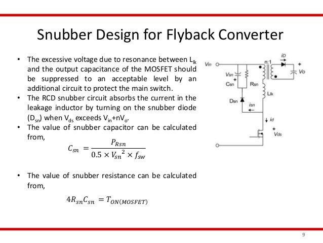
RC snubber design An RC snubber, placed across the switch as shown in figure 4, can be used to reduce the peak voltage at turn-off and to damp the ringing. In most cases a very simple design technique can be used to determine suitable values for the snubber components (R s and C s). In those cases where a more opti. Simple RC Snubber This is probably the most widely used snubber and is applicable for both rate-of-rise control and damping. In inductively clamped topologies, where there is still some stray inductance, the RC snubber can be used to reduce the peak power dissipation in the switch by controlling the rate-of-rise of drain voltage. Your RC Snubber is: V 0 = open circuit voltage I pk = R S = snubber resistance S C s = snubber capacitance And the peak dV/dt is: dV/dt pk = While for a sinewave excitation voltage, rms current in amps is the familiar: f = frequency in Hz I rms = 2πfCVrms x 10-6 C = capacitance in µF V = voltage in Vrms.
Calculates the impedance of the resistor and capacitor in series. | |||
[1] 2021/05/10 19:43 60 years old level or over / Self-employed people / A little /
[2] 2021/03/08 21:20 30 years old level / High-school/ University/ Grad student / Useful /
[3] 2020/05/21 01:01 20 years old level / High-school/ University/ Grad student / Very /
[4] 2020/01/10 05:03 20 years old level / High-school/ University/ Grad student / Not at All /
[5] 2019/03/21 02:23 60 years old level or over / A retired person / Useful /
[6] 2018/02/24 01:50 Under 20 years old / High-school/ University/ Grad student / Very /
[7] 2018/01/23 10:58 Under 20 years old / High-school/ University/ Grad student / Very /
[8] 2017/12/03 17:59 60 years old level or over / A retired people / Very /
[9] 2017/11/24 00:51 50 years old level / An office worker / A public employee / Very /
[10] 2017/11/13 08:53 30 years old level / An engineer / Very / Thank you for your questionnaire. To improve this 'Impedance of R and C in series Calculator', please fill in questionnaire.
| |||